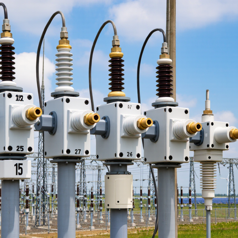
| Equipment Type | Outdoor expulsion fuse cutout with a removable fuse carrier | Provides visible isolation and overcurrent protection for overhead distribution transformers, capacitor banks, and feeder branches. | Confirm that the construction and test requirements match the applicable utility specification and installation environment. |
| Applicable Product Standard | IEC 60282-2 for expulsion fuses, or IEEE C37.41 and IEEE C37.42 for distribution-class fuse cutouts and fuse links | These standards address ratings, design requirements, testing, and performance of high-voltage expulsion fuse equipment. | Request the exact edition of the standard used for type testing and routine production checks. |
| System Voltage Class | Common reference classes: 15 kV, 27 kV, and 38 kV | The cutout voltage rating must be equal to or greater than the highest continuous line-to-line system voltage and suitable for temporary overvoltage conditions. | Check rated maximum voltage, power-frequency withstand voltage, and lightning impulse withstand voltage. |
| Typical Rated Maximum Voltage | 15.5 kV for 15 kV-class systems; 27 kV for 27 kV-class systems; 38 kV for 38 kV-class systems | Using the correct maximum voltage prevents insulation stress and coordination problems. | Do not select only from the nominal system voltage; compare the manufacturer's rated maximum voltage with the network design voltage. |
| Continuous Current Rating | Common cutout body ratings include 100 A and 200 A; higher ratings may be available for special designs | The cutout body and terminals must carry the expected continuous load without excessive heating. | Select a rating above the calculated maximum continuous load and verify temperature-rise test data. |
| Fuse-Link Current Rating | Typical distribution fuse-link ratings range from approximately 1 A to 200 A, depending on the fuse-link design and standard | The fuse link determines overload protection and must coordinate with transformer inrush, feeder load, and downstream protection. | Use time-current curves rather than selecting only by the nominal ampere value. |
| Fuse-Link Speed | Fast links, commonly identified as K-type in IEEE-based systems, or slower links, commonly identified as T-type | Fast and slow characteristics provide different responses to temporary overloads, transformer inrush, and downstream faults. | Compare minimum-melting and total-clearing curves with the protected equipment and coordination study. |
| Interrupting Rating | Common distribution cutout values are approximately 8 kA to 12.5 kA symmetrical RMS, with higher ratings available in specific designs | The interrupting rating must exceed the available fault current at the installation point. | Obtain the prospective short-circuit current from the network study and check the manufacturer's certified interrupting test rating. |
| Lightning Impulse Withstand | Typical reference values include 95 kV for 15 kV-class equipment, 125 kV for 27 kV-class equipment, and 150 kV for 38 kV-class equipment | Adequate impulse withstand helps the cutout tolerate lightning and switching surges on overhead networks. | Confirm the exact impulse withstand value, test waveform, and phase-to-ground configuration. |
| Power-Frequency Withstand | Typical one-minute dry withstand values are approximately 35 kV for 15 kV-class, 50 kV for 27 kV-class, and 70 kV for 38 kV-class equipment | This rating indicates the insulation capability under sustained power-frequency test voltage. | Check whether wet withstand requirements apply to the intended outdoor installation. |
| Creepage and Pollution Performance | Select an outdoor insulator profile suitable for the site's pollution severity; use the applicable IEC 60815 creepage guidance where relevant | Salt, dust, industrial contamination, and moisture can cause surface leakage and flashover. | Provide altitude, pollution level, coastal exposure, and minimum creepage distance requirements to the supplier. |
| Altitude Capability | Standard ratings are often referenced for installations up to 1,000 m above sea level; higher sites may require derating or special design | Air insulation performance decreases as altitude increases. | State the installation elevation and obtain altitude correction or high-altitude certification when required. |
| Fuse Carrier Operation | Dropout operation should provide a clear visible indication after fuse operation; the carrier should be suitable for the specified live-line tool | Visible operation improves fault identification and maintenance safety on overhead lines. | Verify the carrier length, operating angle, latch design, and compatibility with local utility tools. |
| Mounting and Connection | Common arrangements include pole or crossarm mounting with line and load terminals designed for the specified conductor range | Correct mechanical installation prevents loose connections, terminal heating, and alignment problems. | Check terminal material, conductor range, mounting-hole pattern, line/load orientation, and torque requirements. |
| Environmental Construction | UV-resistant polymer or glazed porcelain insulation; corrosion-resistant hardware suitable for outdoor exposure | Outdoor equipment must withstand sunlight, rain, humidity, temperature cycling, and mechanical vibration. | Review material declarations, corrosion protection, sealing details, and environmental test reports. |
| Transformer Protection Coordination | Select the fuse-link ampere rating and time-current curve to protect the transformer while allowing normal energization inrush | An undersized fuse may operate during energization, while an oversized fuse may provide inadequate transformer protection. | Compare transformer full-load current, inrush current, damage curve, secondary protection, and available fault current. |
| Maintenance and Replacement | Use replaceable fuse links with documented dimensions, current ratings, speed characteristics, and clearing curves | Interchangeable, documented fuse links reduce outage time and prevent incorrect replacement. | Confirm fuse-link compatibility by standard, physical dimensions, ferrule or contact design, and electrical characteristics. |
| Recommended Buyer Documentation | Technical datasheet, dimensional drawing, type-test report, routine-test record, time-current curves, installation instructions, and spare-parts list | Complete documentation allows engineering review, purchasing comparison, installation, and future maintenance. | Require all documents before approval, especially for cross-border projects and regulated utility installations. |
| Best General Selection Approach for 2026 | Prioritize certified electrical ratings, fault-current capability, insulation coordination, fuse-link curves, environmental suitability, and verified interchangeability over purchase price alone. | A cutout is reliable only when its electrical, mechanical, and environmental ratings match the complete distribution system. | Approve the final model only after reviewing the network data, applicable standards, test evidence, and site conditions. |