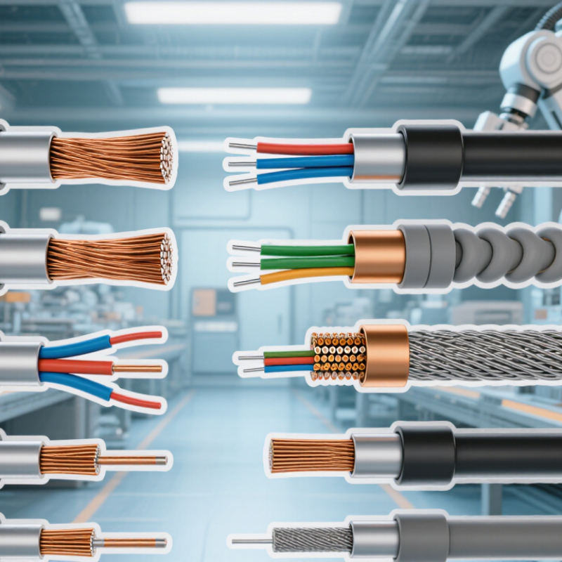
| Unshielded twisted-pair multi-pair cable | Insulated conductors are twisted into pairs; multiple pairs share an outer jacket without metallic screening. | Can suit low-noise, short or well-controlled signal routes when permitted by the system design. | Twisting helps reduce pickup from balanced interference, but the cable has no shield to limit external electromagnetic coupling. | Best considered in electrically quiet areas, separated from power wiring and major noise sources. | Check route proximity to variable-frequency drives, motors, transformers, and switching equipment; confirm project requirements allow unshielded cable. |
| Individually shielded pairs | Each twisted pair has its own screen, commonly foil or braid; a drain wire may be provided for foil screens. | A common choice where individual loop isolation from pair-to-pair coupling is important. | Pair-level screens help reduce crosstalk and interference between neighboring circuits. They do not replace good routing or grounding practices. | Useful in multi-loop runs and installations with several low-level signals in one cable route. | Verify screen coverage, drain-wire details, pair identification, and the specified shield termination method. |
| Overall-shielded twisted-pair cable | Twisted pairs are gathered under one shared metallic screen, typically foil or braid, and an outer jacket. | Often suitable for groups of 4–20 mA loops when the shared-screen arrangement meets the project design. | The overall screen provides a common barrier against external electric-field interference; it offers less pair-to-pair isolation than individual pair screens. | Can be practical for compact installations with moderate interference and coordinated cable routing. | Assess whether circuits can share a screen, and confirm screen continuity, bonding instructions, and the instrument system’s grounding scheme. |
| Individually and overall shielded pairs | Each pair has its own screen, with an additional overall screen around the assembled cable core. | Suitable for sensitive or densely grouped analog loops where both pair-to-pair and external interference control are required. | Provides two levels of screening, but effectiveness still depends on correct termination, bonding, routing, and installation workmanship. | Consider for electrically noisy areas or routes carrying multiple signal circuits, subject to the site’s cable and grounding standards. | Check the construction and termination requirements for both screen levels; confirm the added diameter, stiffness, and cable-tray capacity. |
| Armored instrumentation cable | Instrumentation pairs with a metallic armor layer, which may be combined with individual and/or overall screens. | Loop performance depends mainly on the conductor, pair twist, and screening design; armor is not a substitute for signal shielding. | Metallic armor can provide mechanical protection and may contribute to electromagnetic screening when designed and bonded accordingly. | Consider for exposed routes or locations where impact, crushing, or other mechanical damage is a concern. Armor type must suit the environment. | Specify armor material and coverage, required mechanical protection, cable gland compatibility, environmental exposure, and bonding requirements. |
| Fire-resistant or fire-survivable instrumentation cable | Pairs and screens use materials or constructions selected to meet a defined fire-performance requirement; exact performance depends on the applicable test standard. | May carry 4–20 mA circuits if the electrical, temperature, and installation ratings meet the system requirements. | Screening performance varies by construction; fire performance alone does not establish EMI suitability. | Used where project specifications require a stated level of circuit integrity or fire performance, with compatible supports and installation methods. | Identify the required test standard and performance category; verify that the cable’s fire claim matches the project specification and local rules. |
| Low-capacitance twisted-pair instrumentation cable | Pair geometry and insulation are selected to control conductor-to-conductor and conductor-to-screen capacitance; shielding may be included. | Can be useful on longer runs or where loop response and total circuit capacitance are design concerns; allowable limits depend on the transmitter and input circuit. | Low capacitance does not itself provide EMI protection; evaluate the shield and route separately. | Relevant for long cable lengths, distributed systems, and circuits with defined capacitance limits. | Compare the cable capacitance per unit length with the maximum permitted by the instrument, barrier, isolator, or control-system input. |