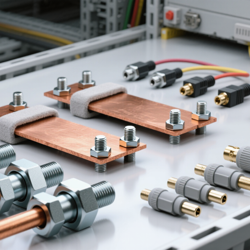
| Bolted busbar connection | Battery racks, DC combiner assemblies, and high-current equipment interfaces | Creates a low-resistance, mechanically secured path between conductive busbars or terminals. | Current capacity, conductor material, joint surface preparation, bolt torque, temperature rise, insulation, and access for inspection. | Suitable for high-current fixed installations; straightforward to inspect and maintain when properly designed. | Requires controlled assembly and adequate clearance. Incorrect torque or contaminated contact surfaces can increase resistance and heating. |
| High-current plug-in connector | Battery modules, rack interfaces, and removable power assemblies | Provides a separable power connection where equipment may need to be installed, replaced, or serviced. | Rated current and voltage, touch protection, keying, mating-cycle rating, contact resistance, temperature range, and connection sequence. | Can simplify modular assembly and replacement compared with hard-wired connections. | Must be matched to the application and correctly mated. Not every plug-in design is suitable for load breaking or energized disconnection. |
| Battery module interconnect | Between cells or modules within a battery pack or rack | Connects series and parallel battery elements to form the required electrical configuration. | Pack architecture, current path, vibration, thermal expansion, insulation, polarity protection, and assembly tolerances. | Supports compact and repeatable battery assembly when designed for the specific module layout. | Compatibility is often specific to the battery design; incorrect polarity or assembly can create serious electrical hazards. |
| Cable lug and terminal connection | Battery cables, inverter terminals, DC distribution, and grounding points | Terminates a conductor for attachment to a stud, terminal, or busbar. | Conductor size and material, lug material, crimp tooling, stud dimensions, corrosion protection, and strain relief. | Widely used and adaptable to many fixed cable connections. | Requires the correct lug, cable, and crimping process. Poor termination can cause loosening, excessive resistance, or overheating. |
| Control and signal connector | Battery management system, rack controllers, sensors, and system communication links | Carries low-voltage control, monitoring, sensing, or communication signals. | Pin assignment, signal type, shielding, ingress protection, locking method, cable routing, and electrical separation from power circuits. | Enables monitoring, control, diagnostics, and communication between BESS subsystems. | Signal integrity can be affected by noise, incorrect pinouts, poor shielding, or unsuitable cable routing. |
| Protective earth and bonding connection | Battery enclosures, racks, cabinets, and other exposed conductive structures | Connects conductive parts to the protective earthing and bonding network as required by the system design. | Applicable electrical codes, fault-current path, conductor sizing, corrosion resistance, continuity, and mechanical security. | Supports electrical safety by providing a designed path for fault current and bonding exposed metalwork. | It is a safety-critical connection and must be installed and verified according to applicable codes and project requirements. |
| DC disconnect or switch connection interface | Battery disconnects, service isolation points, and DC distribution equipment | Connects battery conductors to switching or isolation equipment used to manage and isolate DC circuits. | DC voltage and current ratings, polarity, fault-current withstand, switching duty, enclosure rating, and isolation procedure. | Can provide a defined isolation point for system operation and maintenance when appropriately specified. | Switching capability depends on the device rating and design. A connector or terminal alone should not be assumed to provide safe load-break isolation. |