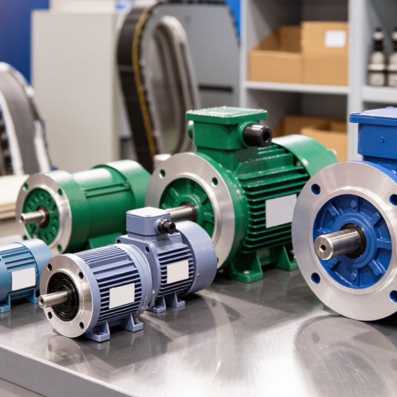
| Foot-mounted (IM B3) | Motor feet are bolted to a base or frame; shaft is generally horizontal. | Pumps, fans, compressors, conveyors, and general-purpose machinery. | Straightforward installation and alignment; widely used where a stable base is available. | Check base rigidity, bolt pattern, shaft alignment, and vibration. Protect the motor appropriately where dust, moisture, or washdown is present. |
| Flange-mounted (IM B5) | A large flange attaches the motor to a machine or housing; mounting is typically at the drive end. | Pumps, gearboxes, process equipment, and machines with a matching flange interface. | Compact drive arrangement that can simplify connection to equipment without a separate motor base. | Confirm flange dimensions, pilot fit, shaft dimensions, and supported loads. The driven machine must provide a sufficiently rigid mounting surface. |
| Face-mounted (IM B14) | A smaller face flange attaches to the machine, commonly using threaded mounting holes. | Compact gear drives, small pumps, packaging machinery, and equipment with limited mounting space. | Space-saving interface suited to compact machinery and smaller drive assemblies. | Verify the face pattern, thread size, pilot, and permissible loads. Do not assume a face mount is interchangeable with a large-flange mount. |
| Foot-and-flange-mounted (IM B35) | Motor includes feet and a large flange; the installation uses the mounting arrangement specified by the machine design. | Applications requiring installation flexibility, including pumps, fans, and industrial machinery. | Offers both foot and flange mounting features, which can accommodate different equipment layouts. | Use only the intended mounting points and confirm that the support carries the motor and driven-machine loads. Check alignment and avoid stressing the housing. |
| Foot-and-face-mounted (IM B34) | Motor includes feet and a smaller face flange for mounting to compatible equipment. | Compact gear units, small process equipment, and installations that may use a base or face interface. | Combines foot mounting with a compact face interface, providing layout options for compatible designs. | Confirm that the machine interface matches the face pattern and that the selected mounting method is supported by the motor documentation. |
| Vertical mounting (for example, IM V1) | Motor is installed with a vertical shaft; the exact arrangement depends on shaft direction and mounting interface. | Vertical pumps, mixers, and machinery designed around a vertical drive shaft. | Fits equipment where a vertical shaft orientation is required and can reduce the need for additional drive-layout changes. | Check the exact mounting code, shaft orientation, bearing arrangement, axial load capacity, and drainage or moisture exposure. Not every horizontal motor is suitable for vertical operation. |
| Special-purpose mounting | Custom brackets, rails, frames, or equipment-specific interfaces. | Mobile equipment, retrofits, confined spaces, and machinery with non-standard interfaces. | Can address unusual space, access, or equipment-integration requirements. | Have the support structure and fasteners checked for load, vibration, alignment, and operating conditions. Confirm the arrangement with the motor and driven-equipment documentation. |