Small private fleet
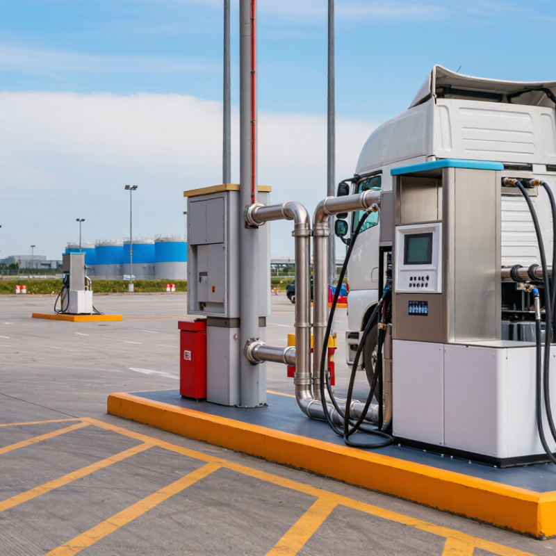
One vehicle fueled at a time | Predictable daily use and limited fueling positions; minimizing unnecessary equipment complexity is often a priority. | A single LNG line and single hose can suit a site that does not require simultaneous LNG dispensing. Confirm the hose reach, nozzle compatibility, and intended vehicle connection. | Choose a system that records the required transaction data and provides clear operator instructions. Confirm that the meter and measurement method meet applicable local trade-measurement requirements. | Check vehicle access, hose routing, emergency-stop locations, ventilation, and the site’s LNG hazard controls against applicable codes and the installation design. | Compare the station’s peak fueling schedule—not just average daily consumption—with the supplier’s stated dispensing performance and vehicle fueling procedure. |
Depot with scheduled return-to-base fueling
Several vehicles use one fueling position in sequence | Reliable turnaround during a defined fueling window, with repeatable procedures for drivers or attendants. | Consider a single-hose unit only if one-at-a-time fueling will not create a queue that disrupts dispatch. Review hose length, parking layout, and ease of positioning vehicles. | Check whether the control system supports the required user authorization, transaction records, and connection to the station’s monitoring or payment system. | Review access control, operator training, emergency shutdown arrangements, and the planned response to leaks or abnormal pressure conditions. | Model the busiest operating period and expected fueling duration. If one position cannot meet the schedule, compare adding a fueling position with changing the operating plan. |
Public or mixed-user station
Multiple vehicle types or operators | Clear instructions, consistent transactions, and compatibility with a wider range of approved vehicles and users. | Verify that the hose, nozzle, breakaway arrangement, and operating sequence are suitable for the vehicles the station will serve. A single hose still serves one connection at a time. | Confirm display readability, units, transaction records, user authorization, and local requirements for commercial measurement and data retention. | Assess vehicle segregation, pedestrian routes, signage, emergency-stop accessibility, and whether staffing or access restrictions are needed. | Document the supported vehicle interfaces and fueling procedures. Do not assume that one nozzle or procedure is suitable for every LNG vehicle. |
Station supplied by an LNG storage tank and pump
Dispenser integrated with on-site equipment | Coordinated operation with the tank, pump, piping, controls, and the station’s required pressure and flow conditions. | Select a dispenser designed for the specified LNG service and compatible with the project’s piping and supply arrangement. Check the required operating envelope with the system designer. | Verify that the meter, temperature or pressure compensation approach where applicable, control logic, and instrument ranges match the full installation design. | Review cryogenic materials, pressure protection, isolation, emergency shutdown interfaces, and applicable hazardous-area and electrical requirements. | Obtain written confirmation of design pressures, temperatures, flow range, connections, and control signals for the complete system—not the dispenser alone. |
Station using a pressure-driven or other non-pump supply arrangement
Operating conditions vary with the supply system | Dispenser performance depends on the upstream system and the actual pressure and temperature conditions available during fueling. | Use a configuration specifically validated for the proposed supply method. Confirm that the supplier’s performance data covers the station’s expected operating conditions. | Check measurement performance across the expected operating range and confirm how faults, interrupted transactions, and abnormal readings are handled. | Review the complete pressure-control and shutdown design, including the interface between the dispenser and upstream equipment. | Request a system-level operating assessment. Do not compare stated flow figures unless the test conditions and measurement basis are equivalent. |