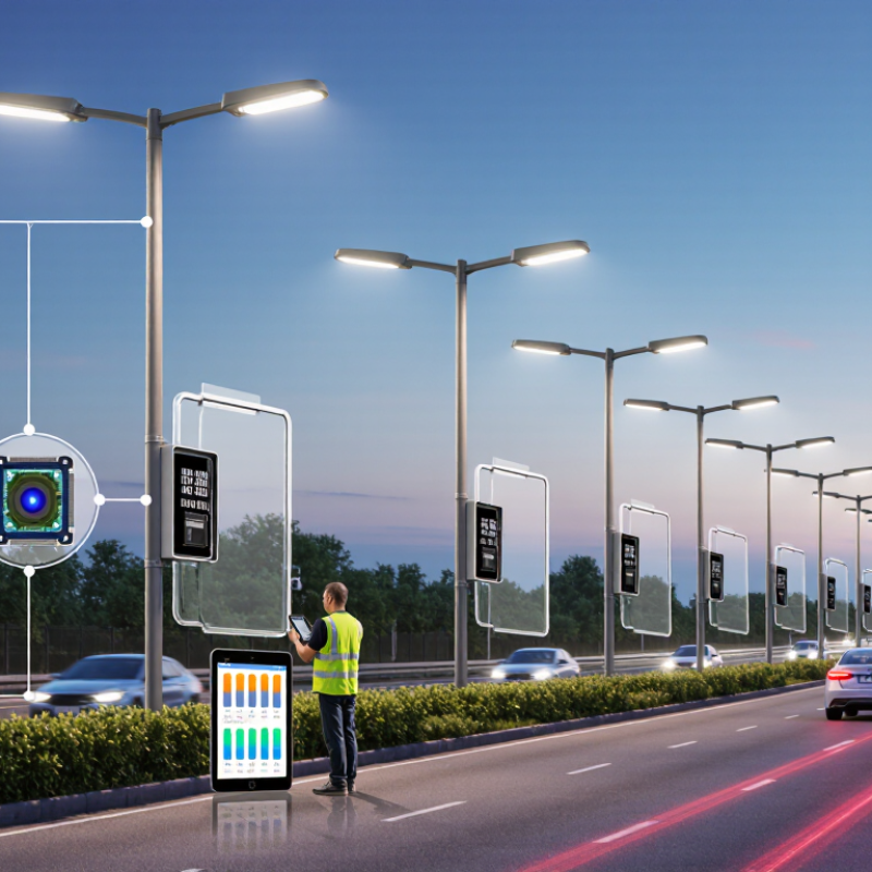
| Primary Sensor Type | Passive infrared (PIR), microwave radar, ultrasonic, ambient-light sensor, or a combined sensor system | PIR detects changes in infrared radiation; radar detects movement through reflected radio waves; ambient-light sensors measure surrounding illuminance. | Sensor selection affects detection reliability, false-trigger resistance, and suitability for different weather and traffic conditions. | Confirm the sensor technology, operating principle, and whether multiple sensors can work together. |
| Typical Detection Range | Approximately 5–15 m for common street-light applications | The sensor identifies movement within its configured coverage zone and sends a control signal to the LED driver. | A suitable range helps prevent missed detection while limiting unnecessary activation outside the roadway or pedestrian area. | Request the tested range, mounting height, detection angle, and environmental conditions used during testing. |
| Detection Angle | Common PIR coverage: approximately 90°–120°; radar coverage varies by antenna and settings | The sensing element monitors a defined horizontal and vertical field of view. | Coverage must match pole spacing, road width, sidewalks, parking areas, or pathways. | Check the actual coverage diagram rather than relying only on the maximum angle stated in a product description. |
| Motion-Detection Response | Typically less than 1 second under normal operating conditions | When movement is detected, the controller changes the LED output from a standby level to a higher lighting level. | Fast response improves visibility and user comfort for pedestrians, cyclists, and drivers. | Review the measured response time and confirm whether delays can be configured. |
| Lighting Control Modes | Full output, dimmed standby, scheduled dimming, motion-triggered boost, and daylight shutoff | The controller adjusts LED current or driver output according to motion, time, and ambient-light signals. | Multiple modes allow the system to balance safety, energy use, and local lighting requirements. | Confirm adjustable brightness levels, hold time, dimming curve, and manual override functions. |
| Common Standby Level | Approximately 20%–50% of rated light output, depending on the project design | The lamp remains partially illuminated when no movement is detected, then increases output when activity occurs. | Maintaining a low standby level can improve perceived safety while reducing energy consumption. | Verify whether the percentage refers to optical output, electrical power, or driver dimming level. |
| Motion Hold Time | Typically adjustable from about 10 seconds to 10 minutes | The light remains at the active level for a preset period after the last detected movement. | Short settings may save more energy, while longer settings reduce frequent switching in busy areas. | Check the available adjustment range and whether the hold timer restarts after each detection event. |
| Potential Energy Reduction | Often approximately 30%–70% compared with continuous full-power operation; project results vary | Energy is saved by dimming the lamp during periods with little or no detected activity. | Actual savings depend on traffic patterns, standby level, active duration, schedule, climate, and installation quality. | Ask for a calculation based on operating hours and measured traffic data, not only a marketing percentage. |
| LED System Efficiency | Many modern outdoor LED luminaires deliver approximately 100–180 lm/W at system level | LEDs convert electrical power into light, while the driver regulates current and supports dimming. | Higher system efficacy can reduce the required wattage for a given roadway lighting level. | Review tested luminaire efficacy, delivered lumens, optical distribution, and driver efficiency together. |
| Typical Rated Power | Approximately 20–150 W for many pedestrian, residential, parking, and local-road applications | Rated power indicates the nominal electrical consumption of the luminaire at full output. | Power selection must match road classification, mounting height, pole spacing, and required illuminance or luminance. | Request a photometric design instead of selecting wattage alone. |
| Outdoor Protection | IP65 or higher is commonly used for outdoor street-light housings; higher protection may be selected for severe exposure | The enclosure limits entry of dust and water that could damage electrical components. | Appropriate ingress protection supports reliable operation in rain, dust, and outdoor environments. | Verify the test standard, certificate scope, and whether the rating applies to the complete assembled luminaire. |
| Impact Resistance | IK08 or IK10 may be specified where resistance to mechanical impact is important | The housing and diffuser are tested against defined impact energy levels. | Higher impact resistance is useful in public areas, parking facilities, and locations vulnerable to vandalism. | Confirm the IK rating for the complete luminaire and identify the tested enclosure components. |
| Operating Temperature | Common outdoor design range: approximately −30°C to +50°C, depending on the product | Thermal design, component selection, and heat dissipation maintain performance across the specified temperature range. | Temperature capability is important for winter climates, hot regions, enclosed coastal areas, and high-power luminaires. | Check the tested ambient-temperature range and expected lumen maintenance at high temperature. |
| Power Supply Compatibility | Common input ranges include 100–277 VAC or 220–240 VAC, with frequency depending on the target market | The LED driver converts incoming AC power into regulated current suitable for the LED modules. | Correct voltage and frequency compatibility reduces flicker, failure risk, and installation problems. | Confirm input voltage, frequency, surge protection, power factor, total harmonic distortion, and dimming interface. |
| Surge Protection | Common specifications include 6 kV or 10 kV; higher ratings may be selected for exposed installations | A surge protective device diverts short-duration overvoltage caused by lightning or grid disturbances. | Street lights installed on long outdoor cable runs can be exposed to electrical surges. | Check whether the rating is line-to-line, line-to-ground, or both, and whether the protection module is replaceable. |
| Sensor Adjustment Functions | Sensitivity, detection range, hold time, standby dimming level, daylight threshold, and active brightness may be adjustable | Settings allow the lighting response to be adapted to traffic density, site layout, and local operating requirements. | Adjustability helps reduce false triggering and improves energy performance after installation. | Confirm whether adjustments are made by remote control, mobile application, wiring, or physical controls. |
| Control and Communication | Standalone control, photocell, 0–10 V, DALI, wired control, or wireless networking may be available | The control interface sends commands between sensors, LED drivers, and optional management software. | Simple standalone systems suit small sites, while networked control supports monitoring and centralized management. | Verify protocol compatibility, communication distance, cybersecurity provisions, and interoperability requirements. |
| LED Lifetime | Often specified as 50,000–100,000 operating hours to a defined lumen-maintenance level | LED lifetime is estimated from thermal performance, component quality, operating current, and lumen-maintenance testing. | Long service life can reduce maintenance visits and replacement costs. | Look for an L70 or equivalent lifetime value, test conditions, ambient temperature, and driver lifetime information. |
| Warranty Period | Common commercial warranty terms range from 3 to 7 years | The warranty defines the supplier's obligations for defects in materials, workmanship, driver, sensor, and housing. | A clear warranty reduces procurement risk and clarifies long-term service expectations. | Review exclusions, replacement procedures, response times, spare-parts availability, and whether the sensor is covered separately. |
| Supplier Qualification | Relevant evidence may include product test reports, quality-management certification, photometric files, electrical safety documentation, and environmental compliance records | Independent testing and documented manufacturing controls help demonstrate repeatable product performance. | Qualification is more reliable when based on verifiable technical documents rather than supplier claims alone. | Request current documents for the exact model, batch, driver, sensor, and configuration being offered. |