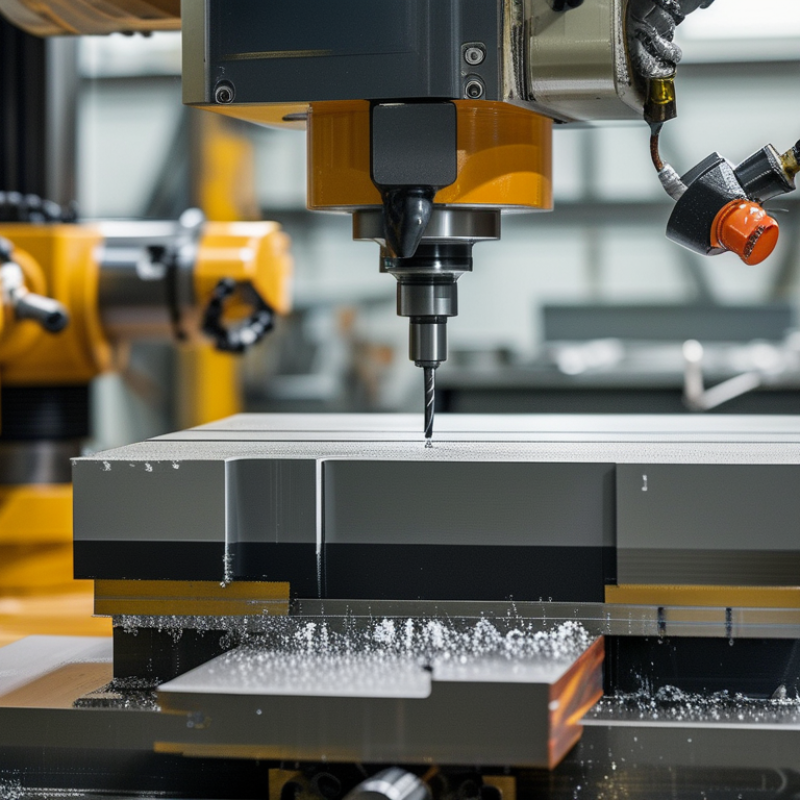
| Fixed-Table, Moving-Gantry | The workpiece remains stationary while the bridge and machining head travel along the longitudinal axis. The crossbeam supports cross-travel and vertical motion. | X: 2–20 m
Y: 1.5–5 m
Z: 0.8–2.5 m | Approximately 5–80 tonnes, depending on table and foundation design. | High | Large structural parts, welded fabrications, molds, energy components, and heavy general engineering work. | Good accessibility, strong floor-level support, suitable for long components, and efficient use of factory space. | Requires accurate rail alignment and a rigid foundation. Moving-gantry mass can affect acceleration and dynamic performance. |
| Moving-Table, Fixed-Gantry | The worktable moves along the longitudinal axis beneath a stationary bridge. The spindle travels across the bridge and vertically. | X: 1–8 m
Y: 1–3 m
Z: 0.6–2 m | Approximately 2–30 tonnes, subject to table travel and guideway design. | Very high | Precision machining, medium-to-large dies, machine bases, and components requiring stable spindle support. | High structural stiffness, relatively stable cutting conditions, and a fixed bridge that can support a heavy machining head. | Needs sufficient floor length for table travel and careful management of moving mass. Loading and unloading may require more clearance. |
| Fixed-Gantry, Fixed-Table | Both the bridge and table are fixed. The machining head moves through the required axes on the crossbeam and vertical column or ram. | X: 2–10 m
Y: 1.5–4 m
Z: 0.8–2.5 m | Approximately 10–100 tonnes or more, subject to table and foundation engineering. | Very high | Heavy-duty roughing, large castings, steel structures, power-generation parts, and high material-removal operations. | Excellent load support, strong resistance to vibration, and no table or bridge travel during cutting. | Work envelope is limited by the stationary structure. Part loading usually needs cranes or dedicated handling equipment. |
| Double-Column, Twin-Drive Gantry | Two vertical columns support the crossrail. Synchronized drives on both sides distribute thrust and reduce crossbeam twisting. | X: 3–20 m
Y: 2–6 m
Z: 1–3 m | Approximately 10–120 tonnes, depending on table construction and foundation capacity. | Very high | Wide workpieces, heavy molds, aerospace structures, shipbuilding components, and large industrial fabrications. | Wide machining coverage, improved crossbeam stability, and better resistance to off-center cutting loads. | Drive synchronization, thermal compensation, guideway protection, and foundation accuracy are critical. |
| Open-Side Gantry | One side of the working area is open or less obstructed, allowing access for long, wide, or irregularly shaped components. | X: 2–15 m
Y: 1.5–4 m
Z: 0.8–2.5 m | Approximately 3–50 tonnes. | Medium to high | Long weldments, rail-related components, frames, structural assemblies, and parts requiring side access. | Flexible loading, easier fixture access, and improved handling of oversized workpieces. | Asymmetric loading can reduce rigidity. The open side may require additional structural reinforcement and guarding. |
| High-Speed Lightweight Gantry | A lightweight bridge, high-speed linear drive system, and compact spindle package are used to prioritize acceleration and rapid positioning. | X: 1.5–8 m
Y: 1–3 m
Z: 0.5–1.5 m | Approximately 0.5–10 tonnes. | Medium | Aluminum parts, composite components, patterns, prototypes, and high-volume trimming or finishing operations. | Fast cycle times, lower moving mass, reduced non-cutting time, and efficient finishing of lightweight materials. | Not normally intended for aggressive heavy roughing. Thermal stability, vibration control, and spindle speed range are important. |
| Five-Axis Gantry Mill | A gantry platform is combined with a swiveling or tilting spindle head, rotary table, or both to provide simultaneous multi-axis machining. | X: 2–12 m
Y: 1.5–4 m
Z: 0.8–2.5 m
Rotary axes: typically ±110° to 360° | Approximately 2–40 tonnes, depending on rotary-axis design and workholding. | High | Complex molds, aerospace structures, impellers, turbine-related parts, and components requiring fewer setups. | Fewer repositioning operations, improved access to angled surfaces, and reduced setup-related errors. | Higher purchase and programming complexity. Rotary-axis accuracy, collision avoidance, calibration, and post-processing must be evaluated. |
| Hybrid Additive–Subtractive Gantry | A gantry machining platform integrates material deposition with conventional milling, drilling, or finishing operations. | X: 2–15 m
Y: 1.5–5 m
Z: 1–3 m | Approximately 2–50 tonnes. | Medium to high | Repair, near-net-shape production, large dies, aerospace structures, and parts requiring localized material addition. | Combines buildup and machining in one setup, reduces material waste, and can shorten repair workflows. | Process qualification, heat input, material compatibility, deposition accuracy, and integrated process monitoring are essential. |
| Modular or Extendable Gantry | Standardized bed sections, rails, columns, or workholding modules can be extended or reconfigured as production requirements change. | X: 3–30 m
Y: 1.5–5 m
Z: 0.8–3 m | Approximately 5–80 tonnes. | Medium to high | Contract manufacturing, changing product sizes, infrastructure components, and facilities with phased capacity expansion. | Scalable layout, easier future expansion, and improved adaptability to changing part dimensions. | Joint alignment, thermal behavior between modules, cable management, and repeatable installation accuracy must be controlled. |