| Pump type and displacement | Confirm the pump technology, nominal displacement, and whether displacement is fixed or variable. | Model documentation, nameplate data, and displacement in cm³/rev. For a given speed, theoretical flow in L/min is displacement in cm³/rev × rpm ÷ 1,000. | Match the required displacement and operating speed; also check the manufacturer’s flow ratings at the intended pressure and fluid viscosity. | Incorrect flow can cause slow actuators, excessive speed, overheating, or inadequate system performance. |
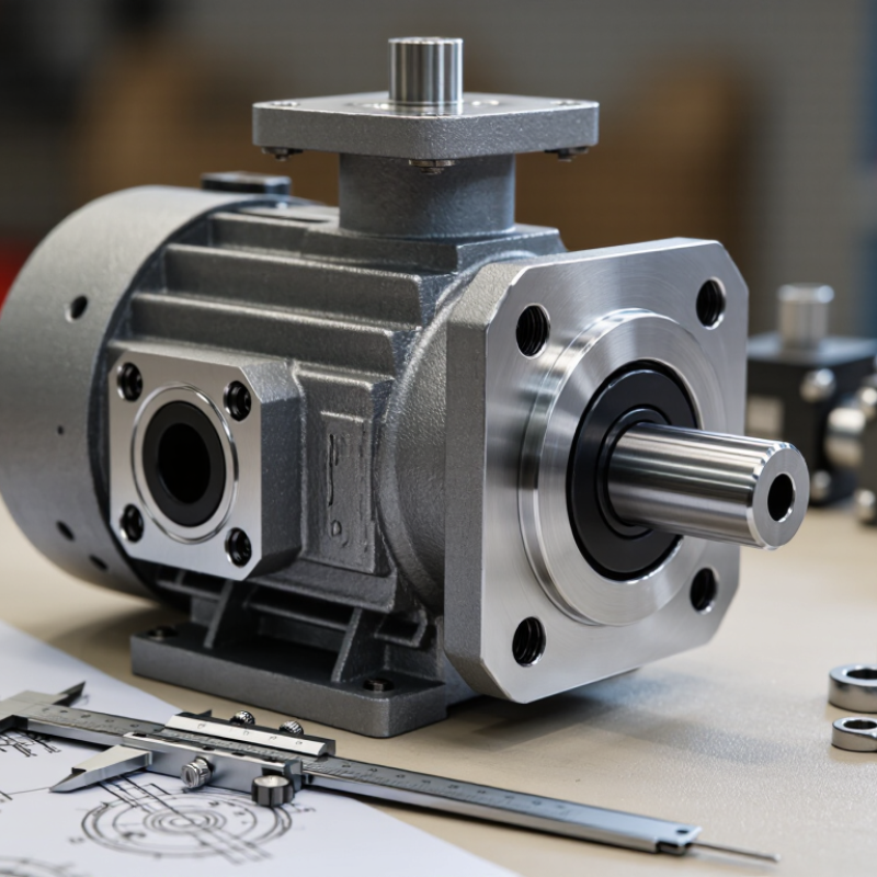
| Shaft and rotation | Compare shaft type, diameter, length, key or spline details, and direction of rotation viewed from the specified end. | Dimensioned shaft drawing; keyway or spline specification; rotation marking or installation documentation. Parallel keys are covered by standards such as ISO 773, where applicable. | Require the same shaft interface and rotation direction, or use a specifically approved coupling or configuration. | A shaft mismatch can prevent coupling, damage the drive, or cause the pump to operate in the wrong direction. |
| Mounting flange and pilot | Check bolt count, bolt-circle or hole spacing, pilot diameter, pilot depth, flange face, and mounting orientation. | Dimensioned interface drawings. ISO 3019-1 covers inch-series mounting flanges and shaft ends; ISO 3019-2 covers metric-series interfaces. SAE J744 is another commonly used hydraulic pump and motor interface standard. | Match the complete mounting interface, not just the number of bolts or the nominal frame description. | Misalignment can create installation problems, coupling wear, vibration, or shaft and bearing damage. |
| Port size and sealing method | Identify inlet and outlet locations, thread or flange type, port orientation, and sealing method. | Port drawing and connection standard. Examples include ISO 1179 for some BSPP-related ports, ISO 6149 for metric ports with O-ring sealing, ISO 6162 for hydraulic flange connections, and SAE J1926 for O-ring-sealed ports. | Match the connection standard, size, sealing surface, and orientation. Do not treat different thread forms as interchangeable because their nominal sizes appear similar. | Leaks, damaged threads, restricted flow, air entry, or an incorrectly connected inlet and outlet may result. |
| Pressure and speed ratings | Compare continuous and intermittent pressure limits, inlet conditions, and minimum and maximum shaft speed. | Published operating limits for the exact pump configuration, including any limits that depend on speed, pressure, or inlet pressure. | Choose a pump whose permitted operating envelope covers the machine’s actual duty cycle, including peak conditions. | Operation outside rated limits can shorten service life or cause premature failure. |
| Control type and settings | For a variable-displacement pump, identify the control function, control port arrangement, pressure setting, and any load-sensing or remote-control requirements. | Control schematic and adjustment range. Confirm whether the system requires pressure compensation, load sensing, remote pressure control, or another specific control function. | Match the control function and signal arrangement; verify settings against the machine circuit and commissioning requirements. | Incorrect control behavior can cause unstable pressure, poor response, excess heat, or failure to meet demand. |
| Fluid and installation conditions | Check fluid type, viscosity range, cleanliness requirements, case-drain needs, and installation orientation. | Pump documentation and system requirements for fluid compatibility, filtration, case drain, and allowable mounting positions. | Confirm that the selected pump is approved for the system fluid and installation conditions. | Unsuitable fluid or installation conditions can reduce lubrication, increase wear, or impair operation. |
| Final fit and commissioning | Verify dimensions and connections against drawings before installation; follow the pump maker’s filling, priming, and start-up instructions. | Approved dimensional drawings, hydraulic circuit, connection details, and commissioning procedure. | Do not rely on a model description alone. Confirm every interface and operating requirement before ordering or starting the pump. | Unverified substitutions can lead to rework, leaks, incorrect rotation, or damage during start-up. |