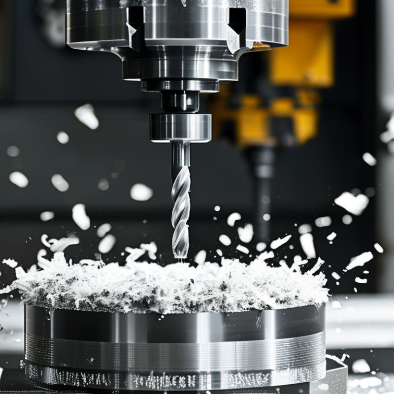
| Aluminum alloys, such as 6061 and 7075 | Polished solid-carbide end mill with a high helix angle | 2–3 | 250–500 | 0.05–0.15 | 1.0–2.0 × cutter diameter for slotting;
up to 3.0 × diameter for adaptive roughing | 0.10–0.50 × cutter diameter | Air blast or minimum-quantity lubrication; flood coolant where suitable | Use a polished flute and strong chip evacuation. Reduce speed or feed if built-up edge or chip welding occurs. |
| Free-machining brass and bronze | Sharp solid-carbide or high-speed-steel end mill with a positive rake | 2–4 | 150–300 | 0.04–0.12 | 0.5–1.5 × cutter diameter | 0.15–0.50 × cutter diameter | Dry machining or air blast is often effective | Avoid excessive rubbing. Use a sharp edge and reduce radial engagement if chatter develops. |
| Low-carbon and mild steel | Solid-carbide or carbide-indexable end mill with a variable helix | 4–5 | 120–220 | 0.03–0.08 | 0.5–1.5 × cutter diameter | 0.10–0.40 × cutter diameter | Flood coolant or directed air, depending on machine and tooling | Use a tougher edge for interrupted cuts. Lower cutting speed when scale, hard spots, or vibration is present. |
| Alloy steel, approximately 30–40 HRC | Coated solid-carbide end mill with a variable pitch | 4–5 | 80–160 | 0.02–0.06 | 0.3–1.0 × cutter diameter | 0.05–0.30 × cutter diameter | Flood coolant or high-pressure air | Use stable tool holding and minimize runout. Reduce radial engagement before reducing feed per tooth. |
| Austenitic stainless steel, such as 304 and 316 | Variable-helix solid-carbide end mill with a strong, sharp edge | 4–5 | 60–120 | 0.02–0.06 | 0.3–1.0 × cutter diameter | 0.05–0.25 × cutter diameter | Continuous flood coolant or high-pressure coolant | Do not dwell in the cut. Maintain sufficient chip thickness to prevent work hardening and rubbing. |
| Gray cast iron | Carbide end mill with a wear-resistant edge | 4–6 | 100–180 | 0.03–0.08 | 0.5–1.5 × cutter diameter | 0.10–0.40 × cutter diameter | Dry machining with strong air blast; coolant may be used if approved for the machine | Protect the machine from abrasive dust. Reduce speed when flank wear or edge chipping increases. |
| Titanium alloys, such as Ti-6Al-4V | Sharp, tough solid-carbide end mill with variable pitch and reduced radial engagement | 4–5 | 30–60 | 0.015–0.04 | 0.2–0.8 × cutter diameter | 0.05–0.15 × cutter diameter | High-pressure flood coolant | Maintain constant tool engagement and avoid heat buildup. Use a rigid setup and replace tools before excessive wear. |
| Nickel-based heat-resistant alloys | Short, rigid solid-carbide or ceramic-compatible cutter selected for the machine | 4–6 | 15–40 | 0.01–0.03 | 0.1–0.5 × cutter diameter | 0.03–0.12 × cutter diameter | High-pressure coolant where compatible with the tool | Use low radial engagement and avoid dwell. These values require confirmation from the tool supplier and machine capability. |
| Hardened tool steel, approximately 45–55 HRC | Aluminum-titanium-nitride-type coated carbide or equivalent hard-milling cutter | 4–6 | 40–80 | 0.01–0.04 | 0.1–0.5 × cutter diameter | 0.03–0.15 × cutter diameter | Dry air blast or controlled coolant, according to tool guidance | Use a rigid machine and short tool overhang. Reduce speed if heat, chipping, or excessive tool wear appears. |
| Core Calculations: Spindle speed, n = (1,000 × Vc) ÷ (π × D); Table feed, Vf = n × z × fz. Here, Vc is cutting speed in m/min, D is cutter diameter in mm, z is the number of flutes, and fz is feed per tooth in mm/tooth. |
| The values above are practical starting ranges for carbide milling and should be validated with the cutter geometry, workholding rigidity, machine power, tool diameter, material condition, and manufacturer's technical data. When increasing material removal rate, adjust radial engagement, axial depth, cutting speed, and feed together rather than changing only one parameter. |