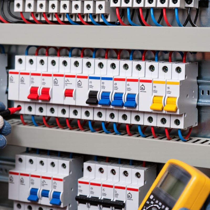
| Protected conductors | 1P, 2P, 3P, or 4P | The number of poles should correspond to the live conductors that must be disconnected during overcurrent protection or isolation. | Confirm the supply arrangement, earthing system, local wiring rules, and whether the neutral must be switched or protected. |
| Single-phase line circuit | 1P or 1P+N | A 1P device generally protects the line conductor only. A 1P+N device disconnects the neutral as well, while the neutral pole may be switched rather than overcurrent-protected depending on the design. | Use 1P+N where simultaneous disconnection of line and neutral is required or preferred. Verify the manufacturer’s neutral-pole switching arrangement. |
| Single-phase line-to-line circuit | 2P | Both live conductors require coordinated overcurrent protection and simultaneous disconnection. | Check the rated voltage between conductors and ensure both poles have the required interrupting capability. |
| Three-phase circuit without neutral | 3P | All three phase conductors are monitored and disconnected together. The device must be suitable for the system voltage and fault level. | Typical for balanced three-phase motors, heaters, and distribution circuits where no neutral conductor is used. |
| Three-phase circuit with neutral | 3P+N or 4P | The three phases are protected against overcurrent. The neutral pole may be switched and may be non-protected, depending on the device construction and installation requirements. | Use a four-pole arrangement when neutral disconnection is required. Do not switch the neutral alone; verify simultaneous operation. |
| Neutral conductor protection | Protected or switched neutral | Neutral overcurrent protection depends on conductor sizing, harmonic currents, earthing arrangement, and applicable installation standards. | Follow the project wiring rules and verify whether reduced-size or high-harmonic neutral conductors require dedicated protection. |
| Rated current (In) | Selected in amperes | The rated current must not exceed the allowable current-carrying capacity of the cable after applying installation, ambient-temperature, grouping, and thermal correction factors. | As a basic design check, ensure the load current is no greater than the protective-device rating and that the protective-device rating does not exceed the corrected cable capacity. |
| Voltage rating (Ue) | AC or DC voltage specified by the manufacturer | The operational voltage rating must be equal to or higher than the circuit voltage. DC applications may require specific polarity, series-pole arrangements, or dedicated testing. | Check the marking for the exact AC/DC voltage, number of poles in series, polarity requirements, and applicable utilization conditions. |
| Short-circuit breaking capacity | Icu and, where applicable, Ics | Under IEC 60947-2, Icu is the ultimate short-circuit breaking capacity. Ics is the service short-circuit breaking capacity and is expressed as a percentage of Icu. | Determine the prospective short-circuit current at the installation point. Select a device with adequate breaking capacity at the actual system voltage and configuration. |
| IEC 60947-2 compliance | Declared conformity to IEC 60947-2 | Verify rated voltage, rated current, breaking capacities, temperature-reference conditions, insulation ratings, terminal requirements, and test declarations. | Request the applicable datasheet or declaration of conformity. Do not assume that a device intended for household use has the same ratings or test basis as an industrial circuit breaker. |
| Insulation ratings | Ui and Uimp | Ui is the rated insulation voltage. Uimp is the rated impulse withstand voltage. These values support insulation coordination and overvoltage protection design. | Compare the device ratings with the installation’s overvoltage category, system voltage, and surge-protection scheme. |
| Overcurrent trip characteristic | Thermal-magnetic or electronic | The long-time and instantaneous response must protect the cable while tolerating normal inrush current from transformers, motors, LED drivers, or capacitive loads. | Use the manufacturer’s time-current curve. B, C, and D designations are commonly associated with IEC 60898-1; for IEC 60947-2 devices, use the declared trip settings and curves. |
| RCD arrangement | Separate RCD, RCBO, or upstream/downstream combination | An MCB provides overcurrent protection but does not provide residual-current protection. An RCD or RCBO must be selected separately when protection against earth-leakage current is required. | Confirm whether the circuit needs additional protection, fault protection, or only fire-risk protection, and select the appropriate residual-current rating. |
| RCD residual operating current (IΔn) | Common values include 30 mA, 100 mA, and 300 mA | A lower residual-current threshold generally provides more sensitive additional protection but can increase nuisance tripping when cumulative leakage is high. | Use the value required by the installation rules and equipment application. Coordinate with normal leakage current and the upstream/downstream protection scheme. |
| RCD type | AC, A, F, or B | Type AC detects sinusoidal AC residual current. Type A also detects pulsating DC residual current. Type F is intended for certain single-phase frequency-controlled loads. Type B can detect smooth DC and a wider range of residual currents. | Match the RCD type to the connected equipment, especially variable-speed drives, photovoltaic inverters, EV charging equipment, UPS systems, and power-electronic converters. |
| RCD time selectivity | Instantaneous or time-delayed upstream RCD | Selective coordination requires compatible operating-time ranges and residual-current ratings. A time-delayed upstream device can allow a downstream RCD to clear a fault first. | Use manufacturer-published selectivity tables and avoid relying only on nominal current values. Verify the complete upstream/downstream combination. |
| RCD and MCB coordination | Separate devices or an integrated RCBO | The RCD must be protected against overload and short circuit unless its construction includes the required overcurrent function. An MCB and RCD must also be compatible with the available fault current. | Check the RCD conditional short-circuit rating, backup-protection requirements, terminal compatibility, and manufacturer coordination data. |
| Discrimination with upstream protection | Current or time selectivity | The downstream breaker should clear a fault without unnecessarily opening the upstream breaker, within the intended fault-current range. | Compare time-current curves and certified selectivity tables for the exact device pair, ratings, and prospective fault current. |
| Terminal and conductor compatibility | Cable size, conductor material, and tightening torque | The terminal must accept the conductor type and cross-sectional area. Incorrect stripping length, torque, or conductor preparation can cause overheating or unreliable operation. | Follow the marked terminal range and specified tightening torque. Check temperature derating when multiple devices are installed together. |
| Ambient temperature and grouping | Reference temperature with correction factors | Thermal-magnetic trip performance and current-carrying capacity can change with ambient temperature, enclosure conditions, and adjacent energized devices. | Apply the manufacturer’s derating tables for the actual enclosure, mounting orientation, ambient temperature, and number of loaded circuits. |
| Isolation suitability | Suitable for isolation or switching only | A circuit breaker intended for isolation must meet the relevant requirements for isolating distance, contact indication, and all-pole disconnection. | Check the product marking and technical documentation rather than assuming that every miniature circuit breaker is suitable for isolation. |
| Verification before installation | Design review and commissioning tests | Correct selection depends on load current, conductor capacity, prospective fault current, pole arrangement, RCD requirements, and coordination data. | Verify polarity, continuity, insulation resistance, protective-conductor continuity, RCD operation, torque, labeling, and compliance with applicable national installation regulations. |