Navigation

The C.L. Smith Blog

How to Choose the Right USB C Bulkhead Connector

A USB C Bulkhead Connector looks simple from the front: a port, a flange, and two mounting screws. The real choice is made behind the panel. Cable length, signal rate, power delivery, sealing, and mounting depth must all suit the equipment. Miss one, and a fast port can become a slow, unreliable one.

The USB Implementers Forum’s USB Power Delivery 3.1 specification supports power levels up to 240 watts. Its USB4 Version 2.0 announcement describes data rates up to 80 Gbps under supported configurations. These figures are useful benchmarks, not promises for every bulkhead assembly. The connector, cable, host, and device must all support the intended performance. Jeff Ravencraft, USB-IF president and COO, has described USB Type-C as “the one connector that has it all.” That versatility makes careful selection more important, not less.

Check the datasheet for supported data rates, current, voltage, panel thickness, and any stated environmental rating. A metal enclosure may need grounding continuity; a damp installation needs a specifically rated seal. Measure the space behind the panel, too. A connector that fits the hole may still collide with a nearby board. Fit matters. A tidy specification sheet can still mislead if it omits the cable or mating conditions. This guide explains how to compare options, verify claims, and choose a USB C Bulkhead Connector that performs reliably in its actual installation.

How to Choose the Right USB C Bulkhead Connector

Define Power, Data, and Video Needs for USB-C’s 24-Pin Interface

USB-C’s 24 contacts support several functions, but a connector’s shape does not guarantee every one. Define the required voltage, current, data rate, and video format before choosing a bulkhead part. The USB Implementers Forum’s USB Power Delivery Specification Revision 3.1 (2021) allows power delivery up to 240 W. That is a ceiling, not a promise. The connector, cable, and host must all support the intended power level.

For data, specify the protocol and minimum throughput, rather than asking for “fast USB.” USB4 Version 2.0, published by the USB Implementers Forum in 2022, supports rates up to 80 Gbps. A panel connector must preserve signal integrity at the chosen rate, especially across a long cable or a vibration-prone enclosure. Check the datasheet. Confirm supported protocols, lane configuration, and tested cable length; pin count alone tells you little.

Video needs a separate check. VESA’s DisplayPort Alternate Mode materials describe video over USB-C, with lane allocation affecting available data bandwidth. Four high-speed lanes can prioritize video; two lanes can leave capacity for USB 3 data. That trade-off is easy to miss. I would verify the host’s output mode and display resolution together, then confirm the bulkhead connector supports that exact configuration. Product tables can be vague, and “USB-C compatible” is not enough evidence.

How to Choose the Right USB C Bulkhead Connector - Define Power, Data, and Video Needs for USB-C’s 24-Pin Interface

Decision Area Typical Requirement or Capability What to Check in the Bulkhead Connector Practical Selection Guidance
USB-C interface A full USB-C receptacle has 24 contact positions, including power, ground, configuration-channel, USB 2.0, and high-speed signal contacts. Confirm the contact population and internal wiring support the functions required; a USB-C shape alone does not guarantee every USB-C feature. Specify the required power, data, and video functions before choosing a panel-mount or bulkhead part.
Basic data USB 2.0 supports signaling up to 480 Mb/s. Check that the USB 2.0 D+ and D− paths are connected and that the assembly is specified for USB 2.0 operation. Suitable for many control, peripheral, and low-bandwidth applications. Do not assume SuperSpeed data is available.
SuperSpeed data USB 3.2 Gen 1x1 supports up to 5 Gb/s; USB 3.2 Gen 2x1 supports up to 10 Gb/s. Verify that the required high-speed differential pairs are routed through the connector and that the assembly is rated for the target data rate. Bulkhead transitions, cable length, and signal quality can affect performance. Check the complete installed channel, not just the receptacle.
USB4 data USB4 systems can support 20 Gb/s or 40 Gb/s, depending on the host, device, cable, and implementation. Require explicit USB4 compatibility and suitable high-frequency signal-integrity performance for the complete assembly. Do not infer USB4 support from a 24-pin connector or USB-C form factor alone.
Standard power USB-C can provide 5 V in basic configurations; actual current depends on the source, device, cable, and applicable charging or USB Power Delivery rules. Check the connector assembly’s rated current, contact resistance, temperature rise, and wire or PCB termination limits. Use the lowest-rated component in the power path to determine the allowable operating current.
USB Power Delivery USB Power Delivery can support negotiated power levels up to 240 W (48 V at 5 A) with compatible USB PD Extended Power Range equipment. Confirm the connector, cable, wiring, and system are rated for the intended voltage and current. Power negotiation also requires appropriate CC circuitry. For currents above 3 A, use a suitable electronically marked cable and verify that every part of the assembly supports the intended PD profile.
Video output USB-C video commonly uses DisplayPort Alternate Mode. Available resolution and refresh rate depend on the source, display, link configuration, cable, and display stream compression support. Check that the required high-speed lanes and configuration-channel functions are supported, and confirm the assembly is designed for the chosen video mode. DisplayPort Alternate Mode can use two or four high-speed lanes. The lane allocation affects whether USB 3.x data can operate at the same time.
Orientation and signal routing The reversible USB-C plug can be inserted in either orientation; high-speed and alternate-mode operation require the system to handle the applicable pin assignments. Review the connector pinout, orientation handling, and any required switching or retiming in the host design. Ask for a pinout and functional specification rather than relying on a generic “USB-C compatible” description.
Mechanical and environmental fit Panel thickness, mounting style, mating access, vibration, and exposure to dust or moisture vary by installation. Check cutout dimensions, fastening method, mating-cycle rating, strain relief, and any stated ingress-protection rating for the installed configuration. An ingress-protection rating is not automatic; confirm whether it applies when mated, unmated, or only with a protective cap.
Final specification Define the required maximum power, data rate, video mode, cable length, and environmental conditions. Request documentation for pin assignment, electrical ratings, supported protocol, mechanical dimensions, and environmental limits. Validate the complete path—from source through bulkhead and cable to the destination—under the intended operating conditions.

Select Power Capacity: USB PD 3.1 EPR Supports Up to 240 W

When choosing a USB-C bulkhead connector for high-power use, treat 240 W as a system target, not a promise printed on the part. USB PD 3.1 EPR can deliver up to 240 W at 48 V and 5 A, but the source, sink, cable, and connector must all support the required operation. A lower-rated cable or contact can limit the whole connection. Check the connector’s voltage and current ratings, not just its USB-C shape.

Heat matters. A bulkhead connector sits in a panel, where airflow may be limited and nearby materials can hold warmth. Review contact resistance, wire gauge, mounting method, and temperature ratings. Then test the assembled connection under a representative load, checking for unusual temperature rise or intermittent power.

A neat specification sheet can still hide a weak detail. It is easy to focus only on wattage; I would also inspect how firmly the connector mounts and how its contacts age with repeated plugging. Measure, don’t assume. If the product does not clearly document EPR capability, choose a more clearly rated option rather than treating 240 W as interchangeable with any USB-C connection.

Match Data Rates: USB4 Supports Up to 40 or 80 Gbps by Version

Choosing a USB-C bulkhead connector starts with the data rate your equipment actually needs. USB4 can support up to 40 Gbps in earlier versions and up to 80 Gbps with USB4 Version 2. A USB-C-shaped opening alone does not guarantee either speed. The connector, internal wiring, cable, and connected devices must all support the target rate. One weak link can limit the connection.

Check the connector’s specification sheet for its supported USB version and data rate. Then consider cable length and installation conditions. A short, well-shielded connection is generally easier to maintain at high speeds than a long run routed beside power cables. Some USB4 Version 2 configurations can use asymmetric bandwidth, so confirm that the specific host and device support the mode you need. I have seen connector shape mistaken for performance; it is an easy assumption to make, but a costly one.

Tips: Match every part of the connection. Ask the supplier for verified data-rate specifications, not just “USB-C compatible.” If possible, test the assembled link with your own devices. Check twice. A bulkhead connector may fit neatly and still fall short of the required speed.

Choose Mounting Style, Panel Cutout, Cable Length, and Strain Relief

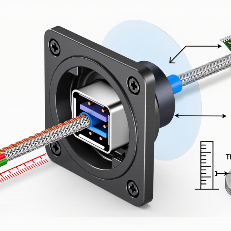
A USB-C bulkhead connector should match the panel and the cable’s real working conditions. Choose a mounting style that suits the enclosure: threaded versions can clamp securely, while flange-mounted types may need more space for screws. Check the panel cutout dimensions against the connector drawing, including any tolerances. A hole that is slightly too large can leave the connector loose; one that is too small may damage the panel during installation. Measure twice. I have seen this simple check save more time than rushing to fit the part.

Tips: Confirm panel thickness and clearance behind the connector. Leave enough cable length for routing and service, but avoid excess cable that can snag or press against nearby parts. Check whether the cable exits straight or at an angle.

Strain relief matters when the cable may be pulled, bent, or moved during maintenance. Look for a design that supports the cable without forcing a tight bend near the connector. Match the relief to the cable’s diameter, and inspect how it attaches to the panel or housing. A compact setup can look neat, but it may be harder to service later. That trade-off is easy to overlook. Review the assembly in its actual enclosure before ordering, since drawings cannot show every routing constraint.

Specify Environmental Sealing Using IEC 60529 IP Ratings

For a USB-C bulkhead connector, an IP rating describes protection against dust and water under specified test conditions. Under IEC 60529, the first digit indicates protection from solid objects, while the second indicates water ingress protection. For example, IP67 includes dust-tight protection and temporary immersion testing. Check the actual test depth and duration before treating that rating as suitable for your installation.

The connector is only one part of the seal. A panel gasket, mounting surface, cable entry, and mating plug can all create leak paths. Confirm whether the stated rating applies when the connector is mated, unmated, or fitted with a protective cap. Small details matter. A scratched panel or uneven mounting pressure may compromise sealing, even when the connector itself has a strong rating.

Choose a rating based on exposure: splashes near an indoor control panel differ from rain, washdown, or immersion. Allow for the real installation, not just the product sheet. A higher rating is not automatically better if the assembly has not been tested in that configuration. It is also easy to overlook condensation and temperature cycling; IP testing alone does not describe every environmental stress. If failure would be costly, verify the complete mounted assembly with suitable testing.

Back to top