| 1 | Match the Frequency Range | Identify whether the interference is mainly low-frequency magnetic noise, electric-field noise, radio-frequency interference, or a combination of these. | Shielding effectiveness is frequency-dependent and is normally expressed in decibels (dB). Results should include the tested frequency range and test configuration. Common evaluation methods include ASTM D4935, IEEE 299, and IEC 62153-4-3. | Do not compare two dB values unless the frequency, test method, sample geometry, and termination conditions are comparable. Select a sleeve that has verified performance across the actual operating band. |
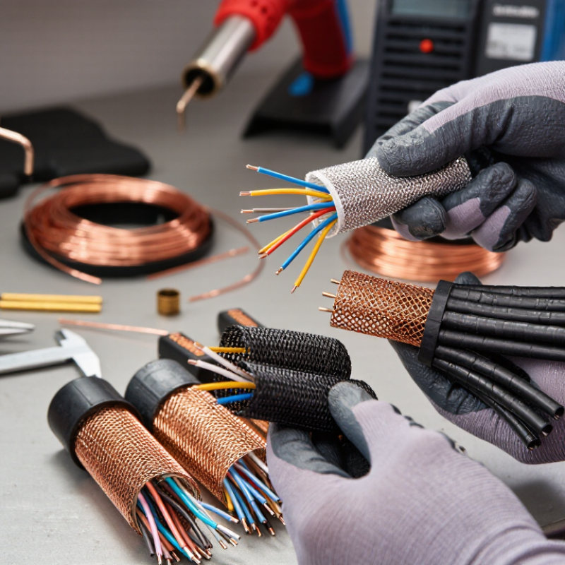
| 2 | Check Shield Construction | Review the conductor type, braid or knit structure, coverage, openings, and whether the sleeve is conductive throughout its length. | Common conductive materials include copper, tin-plated copper, stainless steel, aluminum, and conductive fibers. Bulk electrical conductivity at approximately 20°C is about 5.8 × 10⁷ S/m for copper, 3.5 × 10⁷ S/m for aluminum, and 1.4 × 10⁶ S/m for stainless steel; the finished sleeve performance also depends on geometry and contact resistance. | Choose a construction with sufficient coverage and stable contact between adjacent filaments. A highly conductive material does not automatically provide the best shielding if the sleeve has large openings or poor termination. |
| 3 | Verify Electrical Continuity | Confirm that the sleeve can be connected to the equipment chassis, connector backshell, shield drain, or designated grounding point. | Request sleeve resistance or surface-resistance data, test current, test length, and measurement conditions. Measure continuity after installation and after flexing because movement can increase contact resistance. | For a continuous shield, use a low-resistance, mechanically secure termination. Avoid relying on paint, oxide layers, loose clamps, or accidental contact with nonconductive cable jackets. |
| 4 | Evaluate Electrical Compatibility | Determine whether the sleeve is intended to be grounded, floating, or electrically isolated from nearby conductors and whether it could create an unintended current path. | Check insulation voltage ratings, dielectric requirements, creepage and clearance requirements, and the system grounding architecture. A conductive sleeve should not contact exposed live conductors unless the design specifically provides the required insulation and protection. | Use an insulating over-sleeve or barrier where abrasion protection and electrical separation are both required. Confirm compatibility with the cable voltage, current, connector design, and applicable safety requirements. |
| 5 | Size for Coverage and Installation | Measure the cable bundle diameter, connector clearance, bend radius, and required expansion or compression during installation. | Record the minimum and maximum applicable inside diameter, expansion ratio, wall thickness, cut length, and termination allowance. The sleeve should cover the required cable length without excessive gaps or overstretching. | Select a size that fits the installed bundle rather than only the nominal cable diameter. Excessive stretching can enlarge openings, while an oversized sleeve can move, wrinkle, or lose reliable termination contact. |
| 6 | Review Environmental Compatibility | Consider operating temperature, humidity, fluids, salt spray, vibration, abrasion, ultraviolet exposure, and chemical contact. | Use the sleeve's documented temperature range, flammability classification, chemical-resistance data, and environmental test results. Material limits vary substantially between metallic, textile, polymer-coated, and plated constructions. | Choose a sleeve whose tested environmental limits exceed the application conditions. For outdoor or high-vibration installations, verify corrosion resistance, coating durability, and resistance to repeated flexing. |
| 7 | Validate the Complete Assembly | Test the sleeve together with the cable, connectors, clamps, grounding points, bends, and adjacent enclosure—not only as a loose sample. | Repeat shielding-effectiveness and continuity checks after installation, bending, vibration, and environmental exposure where applicable. Document frequency, dB result, termination method, cable length, and test configuration. | The termination and cable-entry points often determine the final result. Select the sleeve only after the complete assembly meets the required electromagnetic-compatibility and electrical-safety targets. |