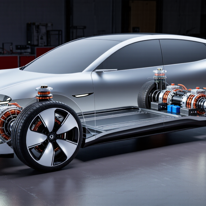
| Motor Architecture | Direct-drive permanent-magnet synchronous motor; optional reduction gearing | Direct drive preferred | Direct drive reduces gearbox losses and packaging complexity, while geared designs can increase wheel torque density. | Motor topology, sectional drawings, electromagnetic design report, and system efficiency map |
| Nominal DC-Link Voltage | 400–800 V DC | 800 V for high-power platforms | Higher voltage can reduce current for the same power level, helping reduce conductor and inverter losses. | Validated voltage range, insulation-coordination report, hipot test, and inverter compatibility data |
| Peak Motor Efficiency | 92–97% | ≥95% | Peak efficiency is normally measured at a specific speed, torque, voltage, and coolant condition; it should not be treated as full-cycle efficiency. | ISO 17025 laboratory report, efficiency map, test temperature, and measurement uncertainty |
| High-Efficiency Operating Area | Approximately 70–90% efficiency over selected operating points | Broad efficiency plateau | A wide high-efficiency area is more meaningful for vehicle energy consumption than a single maximum-efficiency figure. | Full speed-torque-efficiency map covering drive and regeneration quadrants |
| Peak Wheel Torque | 300–1,000 Nm per wheel | ≥600 Nm per wheel | Peak torque supports launch and transient performance. The value must be evaluated together with wheel diameter, vehicle mass, and peak duration. | Dyno test curve, torque sensor calibration, speed range, and peak-duration definition |
| Continuous Wheel Torque | 150–450 Nm per wheel | ≥250 Nm per wheel | Continuous torque is more relevant to sustained gradients, towing, and thermal-limited operation than short-term peak torque. | Continuous torque-speed curve at stated coolant temperature and ambient conditions |
| Peak-Torque Duration | 5–15 seconds | ≥10 seconds | Peak torque is commonly limited by winding temperature, magnet temperature, inverter current, or tire traction. | Time-based overload profile, temperature trace, inverter-current limit, and repeatability data |
| Cooling Arrangement | Liquid jacket, oil spray, or combined stator-and-rotor cooling | Liquid or oil cooling | Liquid and oil cooling generally provide higher continuous power capability than passive air cooling in compact wheel-end systems. | Cooling schematic, flow-rate requirement, pressure drop, heat-rejection capacity, and leakage test |
| Continuous Thermal Load | Approximately 20–60 kW per wheel | Application-dependent | Thermal load depends on duty cycle, road speed, ambient temperature, cooling flow, and allowable winding temperature. | Thermal steady-state test, duty-cycle simulation, thermal network model, and derating strategy |
| Winding Temperature Limit | Typically 150–200°C, depending on insulation system | Verified below the design limit | The insulation thermal class, magnet temperature, bearing temperature, and local hot spots must all be checked separately. | Thermocouple or fiber-optic measurements, thermal-class declaration, and hot-spot analysis |
| Operating Ambient Temperature | Approximately −40°C to +85°C | −40°C to +85°C | Cold-start torque, lubricant behavior, sensor accuracy, and power derating should be verified across the complete temperature range. | Temperature-chamber test report and cold-start/high-temperature performance curves |
| Ingress Protection | IP67 to IP6K9K, depending on configuration | IP6K9K for exposed wheel-end use | IP67 covers dust protection and temporary immersion; IP6K9K additionally addresses high-pressure, high-temperature water jets. | IEC 60529 and ISO 20653 test reports, including connector and cable-entry configuration |
| Regenerative Braking Capability | Typically 20–60% of peak motoring torque | Matched to battery and tire limits | Regeneration is constrained by battery acceptance power, inverter limits, tire-road adhesion, and vehicle brake-control strategy. | Four-quadrant torque map, battery-charge-power limits, and blended-braking validation |
| Functional-Safety Framework | ISO 26262 development process with item definition, hazard analysis, safety goals, and safety mechanisms | ASIL allocation documented | ISO 26262 is a functional-safety standard; compliance depends on the defined item, safety lifecycle, hardware metrics, software process, and safety case. | Safety plan, HARA, FSC/TSC, FMEDA, diagnostic coverage, dependent-failure analysis, and safety manual |
| ISO 26262 Hardware Evidence | SPFM, LFM, PMHF, fault-injection results, and production-control evidence | Third-party assessment available | Hardware-metric targets are determined by the assigned ASIL and system architecture; the supplier should provide assumptions and diagnostic dependencies. | FMEDA, fault-injection report, safety-analysis assumptions, and independent assessment statement |
| Automotive Quality System | IATF 16949-based quality management with APQP, PPAP, FMEA, SPC, and traceability | IATF 16949 certified | Quality certification supports repeatable manufacturing but does not replace product-specific validation or functional-safety evidence. | Current certificate, control plan, process capability data, PPAP package, and change-control procedure |
| Validation Priorities | Efficiency, torque accuracy, thermal endurance, vibration, corrosion, water ingress, EMC, and abuse testing | Full vehicle-duty-cycle validation | Wheel motors experience road shock, unsprung-mass vibration, water splash, debris impact, and repeated thermal cycling. | DV/PV matrix, durability profile, environmental test records, EMC reports, and end-of-line test coverage |