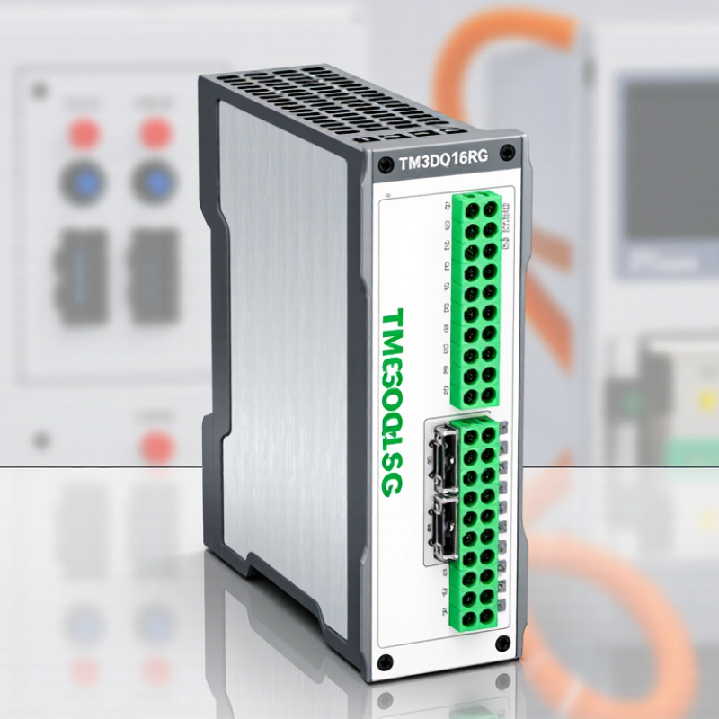
| Module identification | TM3DQ16RG is a programmable-logic-controller expansion module with 16 relay outputs. | It is an output module for switching external loads; it is not a standalone controller. |
| Output technology | Electromechanical relay contacts, typically one normally open contact per output. | Relay outputs can switch AC or DC loads within their specified voltage and current limits. They are not intended for high-speed pulse output. |
| Output count and grouping | 16 outputs arranged in two groups of eight, with separate group common connections. | Check the wiring diagram when selecting a supply and connecting commons; outputs in a group share the applicable common connection. |
| Contact ratings | Rated switching range: 5–250 V AC or 5–30 V DC; maximum switching current: 2 A per output, subject to load and grouping limits. | Verify the current per common, total module loading, load type, and switching frequency against the module’s current technical documentation. |
| Controller compatibility | Designed for use with a controller and expansion system that support the TM3 module interface. | Confirm the controller’s supported expansion modules, available bus capacity, configuration software support, and firmware requirements before installation. It is not universally compatible with every PLC. |
| Installation method | Installed as an expansion unit alongside a compatible controller or other supported expansion modules. | Follow the system’s specified mounting and module-connection procedure. Isolate power before installing, removing, or rewiring the module. |
| Load power and wiring | The relay contacts switch the external load circuit; load power is supplied by the external circuit, not generated by the relay contacts. | Use conductors and protective devices rated for the load. Keep wiring within the permitted voltage and current ratings, and separate wiring as required by local electrical rules. |
| Relay life and switching | Relay contacts are mechanical components and have finite electrical and mechanical life. | Switching life varies with voltage, current, inrush, and load type. Consider contact protection or an interposing device for inductive or frequently switched loads. |
| Commissioning checks | After wiring, verify channel assignments, output logic, load operation, and the controller’s module configuration. | Test outputs under safe conditions before normal operation. Confirm that the application’s fail-safe behavior does not rely on an assumed relay state during power loss. |
| Documentation check | Exact ratings, terminal assignments, environmental limits, and mounting details can depend on the product revision and installation conditions. | Use the module’s current datasheet and wiring diagram as the final reference for design and installation. |