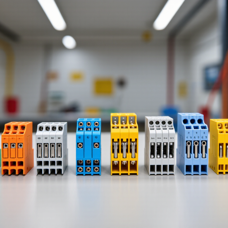
| 1 | Screw-clamp terminal block | A screw presses a clamp plate or conductor against a conductive current bar. | Solid or stranded copper conductors; ferrules may be used where permitted by the manufacturer. | Control panels, machinery, building services, and general-purpose wiring. | Follow the specified tightening torque and conductor-size range. Vibration and maintenance conditions may affect suitability. |
| 2 | Spring-clamp terminal block | A spring maintains pressure on the conductor inserted into the clamp. | Usually solid or stranded conductors; some designs require a ferrule or an operating tool for fine-stranded wire. | Industrial control cabinets, transport equipment, and installations where vibration resistance is important. | Check the permitted wire preparation, insertion method, and conductor cross-section for the specific model. |
| 3 | Push-in terminal block | A conductor is pushed into a spring contact; a release opening or lever is used to remove it when provided. | Commonly solid conductors and stranded conductors fitted with suitable ferrules. | Panel wiring, compact control systems, and high-volume assembly. | Confirm whether bare fine-stranded conductors are accepted and whether a release tool is required. |
| 4 | Barrier terminal strip | Screws secure conductors to separate terminals, with insulating barriers between adjacent connection points. | Typically solid or stranded copper conductors with compatible terminals or lugs. | Appliances, power distribution, equipment wiring, and field connections. | Verify voltage, current, wire range, spacing, and cover requirements; barriers provide separation but do not replace correct circuit protection. |
| 5 | Feed-through terminal block | A conductive element connects a conductor inserted on one side to a conductor inserted on the other. | Solid or stranded copper conductors, depending on the clamp design. | DIN-rail control panels and organized point-to-point wiring. | Check the rated current, voltage, conductor range, and compatibility with the mounting rail and accessories. |
| 6 | Grounding (PE) terminal block | A protective conductor is clamped to a conductive terminal that bonds to a grounded mounting rail or designated grounding point. | Protective earth conductors; allowable conductor types and sizes depend on the terminal design. | Protective bonding in electrical enclosures and control panels. | Use only a terminal designed and rated for protective grounding, and ensure the mounting rail or grounding point is correctly bonded. |
| 7 | Fuse terminal block | Conductors connect through a holder containing a replaceable fuse in series with the circuit. | Solid or stranded conductors compatible with the terminal’s connection system. | Branch-circuit protection and signal or control-circuit protection in panels. | Select the correct fuse type and rating for the circuit. A fuse terminal is not a substitute for verifying the system’s required protection coordination. |
| 8 | Disconnect or test terminal block | A removable link, switch, or test mechanism opens the circuit or provides access for measurement. | Conductors suited to the block’s screw, spring, or other connection mechanism. | Instrumentation, control circuits, and circuits that require isolation or testing. | Confirm the open-state isolation, test access, and circuit rating; follow safe isolation procedures before servicing. |
| 9 | Multi-level terminal block | Two or more electrically separate connection levels are stacked within one terminal assembly. | Solid or stranded conductors compatible with each level’s clamp type. | Space-constrained control panels and dense signal wiring. | Check the number of independent circuits, marking options, accessibility, and applicable voltage rating between levels. |
| 10 | Insulation-displacement (IDC) terminal block | A shaped contact cuts through or displaces insulation to make electrical contact with the conductor. | Usually specified solid conductors or particular wire types and gauges; compatibility is design-specific. | Telecommunications, signal wiring, and applications designed for rapid termination. | Use only with the conductor type and size specified for the IDC contact; incorrect wire selection or insertion can cause an unreliable connection. |