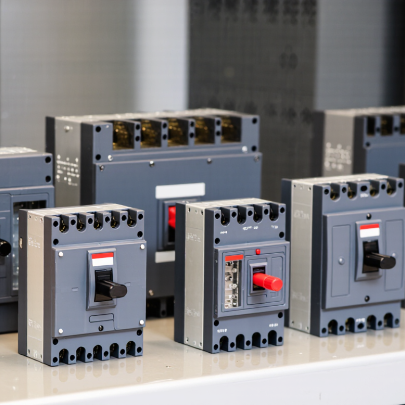
| 1. Product definition | An enclosed circuit breaker is a circuit breaker installed in a protective case or enclosure, often supplied as a self-contained unit for mounting and connection. | The enclosure helps protect people from contact with live parts and can shield the device from specified environmental conditions. It does not, by itself, guarantee suitability for every environment. | Check the product documentation for the breaker type, enclosure construction, intended mounting, and stated environmental limits. |
| 2. Current rating and application | Confirm the rated current, number of poles, system voltage, frequency, and whether the device is intended for the specific circuit and load. | A breaker must be selected for the electrical system and the conductors and equipment it protects. The correct current rating depends on the installation and applicable electrical rules. | Compare the nameplate and technical data with the system design and the applicable local electrical code. |
| 3. Overload protection | Review the breaker’s long-time or thermal protection function and the available trip settings, where adjustable. | Overload protection responds to current above the normal operating level for a sustained period, helping limit overheating of conductors and equipment. | Review trip curves, setting ranges, and coordination requirements. Do not assume every enclosed breaker has adjustable settings. |
| 4. Short-circuit operation | Check how the breaker detects and interrupts high fault current, including its instantaneous or short-time trip functions where provided. | During a fault, the breaker’s contacts separate and an arc is controlled and extinguished by the device’s internal design. The enclosure is not a substitute for the breaker’s interrupting capability. | Consult the manufacturer’s time-current curves and rated short-circuit data for the intended voltage and installation conditions. |
| 5. Interrupting capacity | Verify the rated short-circuit breaking or interrupting capacity at the applicable system voltage. | The breaker must be able to safely interrupt the prospective fault current at its installation point. A rating stated at one voltage should not automatically be applied at another. | Compare the published rating with the calculated or otherwise established prospective fault current and follow the applicable standard. |
| 6. Trip unit and sensing | Determine whether protection is thermal-magnetic, electronic, or another documented design, and identify which protection functions are included. | Trip technology affects available settings, measurement features, and coordination options. Features vary by model and should be verified rather than presumed. | Check the trip-unit specification, protection-function list, setting instructions, and any required configuration tools. |
| 7. Enclosure protection | Review the enclosure’s stated ingress protection, material, corrosion resistance, and suitability for indoor or outdoor use. | Dust, water, corrosive atmospheres, and temperature can affect service life and safety. An IP rating describes specified ingress protection; it does not alone establish all environmental suitability. | Check the enclosure rating and installation conditions. Confirm that covers, cable entries, and fittings preserve the required protection level. |
| 8. Standards and certification | Identify the standards and approvals applicable to the breaker, enclosure, and target market. Examples include IEC 60947-2 and UL 489 for relevant circuit-breaker categories. | Standards and certifications provide a basis for assessing design and test requirements, but requirements differ by product type and jurisdiction. | Request the exact standard edition, certification details, and documentation for the specific model and configuration. |
| 9. Accessories and installation | Assess terminal arrangements, cable-entry options, auxiliary contacts, shunt trips, undervoltage releases, and other accessories where available. | Compatible accessories can support system control and monitoring, while unsuitable connections or installation conditions can compromise performance. | Use the product’s compatibility tables, wiring diagrams, installation instructions, and specified conductor requirements. |
| 10. Testing, support, and lifecycle | Evaluate technical documentation, product traceability, warranty terms, replacement availability, and access to qualified service support. | Reliable documentation and service help with commissioning, maintenance, fault investigation, and future replacement. | Ask for test reports or declarations where applicable, maintenance guidance, spare-part information, and support arrangements for the intended region. |