| Basic operating principle |
Reversible movement of lithium ions |
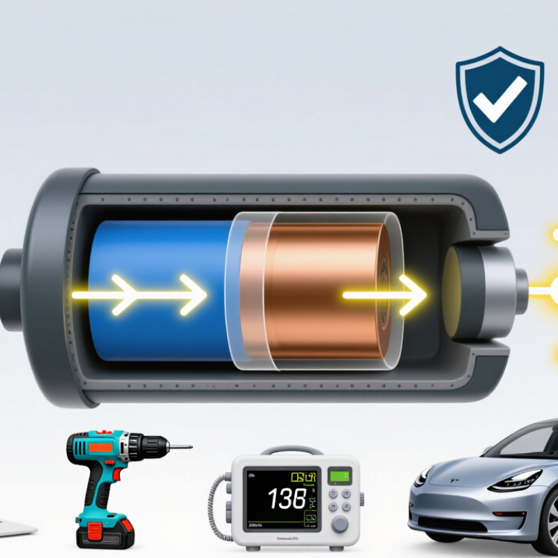
During discharge, lithium ions move from the negative electrode to the positive electrode through the electrolyte, while electrons flow through the external circuit. Charging reverses this process.
|
The controlled movement of ions and electrons produces usable electrical energy.
|
Damage to the separator, electrolyte, or electrodes can cause internal short circuits and rapid heating.
|
| Main cell components |
Negative electrode, positive electrode, separator, electrolyte, and current collectors |
The electrodes store and release lithium; the separator prevents direct contact; the electrolyte transports ions; and the current collectors conduct electrons.
|
Electrode materials, particle size, coating quality, and separator design strongly influence capacity, power, and service life.
|
Manufacturing defects, contamination, or separator damage can increase the risk of an internal short circuit.
|
| Common cell formats |
Cylindrical, prismatic, and pouch |
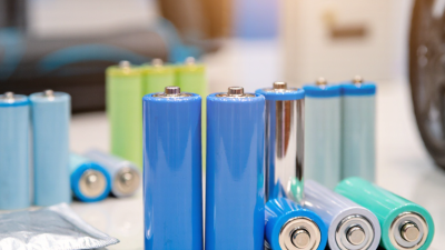
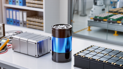
These formats use similar electrochemical principles but differ in mechanical construction, cooling requirements, packaging, and space utilization.
|
Cylindrical cells generally provide robust mechanical packaging; prismatic and pouch cells can use available space efficiently.
|
Pouch cells require effective external restraint, while all formats require protection against crushing, puncture, and overheating.
|
| Nominal voltage |
Approximately 3.2–3.7 V per cell, depending on chemistry |
Nominal voltage is an approximate operating voltage rather than the maximum or minimum cell voltage.
|
Cell voltage determines how many cells must be connected in series to reach a required pack voltage.
|
Charging limits must match the specific cell chemistry and design; a higher nominal voltage does not automatically mean higher safety.
|
| Typical charge voltage |
About 3.65 V for lithium iron phosphate; about 4.20 V for many layered-oxide cells |
The charger normally uses a constant-current phase followed by a constant-voltage phase until the current falls to a specified termination level.
|
Higher charge voltage can increase usable energy but may accelerate side reactions and capacity loss.
|
Overcharging can cause gas generation, lithium plating, overheating, and thermal runaway. A correctly configured battery-management system is essential.
|
| Specific energy |
Approximately 90–280 Wh/kg at cell level, depending on chemistry and design |
Specific energy is the amount of stored energy per unit mass. It is calculated from capacity and voltage relative to cell mass.
|
Higher specific energy can extend operating time or reduce battery mass.
|
Designs optimized for high energy may have less tolerance for abuse, heat, or high charging rates than designs optimized for power.
|
| Energy density |
Approximately 180–700 Wh/L at cell level |
Energy density describes stored energy per unit volume and depends on active materials, packaging, and unused space.
|
Higher energy density allows more energy to fit into a smaller enclosure.
|
Compact, energy-dense cells require careful thermal management and mechanical protection because heat can be concentrated in a smaller volume.
|
| Charge rate |
Commonly 0.5C–1C; some cells are designed for higher rates |
A 1C charge rate theoretically charges a fully discharged cell in about one hour, although actual charging takes longer because of the constant-voltage phase.
|
Higher charging rates reduce charging time but increase polarization, heat generation, and stress on the electrodes.
|
Charging a cold cell or charging above its specified rate can promote metallic lithium plating and create a serious internal short-circuit risk.
|
| Discharge rate |
Commonly 0.5C–3C for energy cells; higher for power cells |
The C-rate expresses current relative to rated capacity. For example, a 2 Ah cell discharged at 1C supplies approximately 2 A.
|
High discharge rates increase voltage drop and heat, reducing temporarily available capacity.
|
Exceeding the specified continuous or pulse current can overheat the cell, damage internal materials, or activate protection devices.
|
| Operating temperature |
Typically about 0–45 °C for charging and −20–60 °C for discharge, subject to cell specifications |
Temperature affects electrolyte conductivity, reaction kinetics, resistance, and the stability of electrode interfaces.
|
Low temperatures reduce power and usable capacity; high temperatures can temporarily improve kinetics but accelerate aging.
|
Charging below 0 °C can cause lithium plating. Sustained high temperature increases the possibility of venting and thermal runaway.
|
| Internal resistance |
Typically a few milliohms to several tens of milliohms for individual cells |
Internal resistance represents opposition to current flow and includes electronic, ionic, and interfacial contributions.
|
Lower resistance improves power delivery, reduces voltage sag, and lowers heat generation during high-current operation.
|
A sudden rise in resistance or a large difference between cells may indicate aging, damage, poor connections, or an unsafe condition.
|
| Round-trip efficiency |
Often approximately 90–98% under moderate conditions |
Round-trip efficiency is the energy recovered during discharge divided by the energy supplied during charging.
|
Higher efficiency reduces energy losses and heat production during repeated cycling.
|
Efficiency decreases at extreme temperatures, high C-rates, high state of charge, and near the end of cell life.
|
| Cycle life |
Approximately 500–5,000+ full equivalent cycles, depending on chemistry and operating conditions |
One full equivalent cycle represents cumulative discharge equal to 100% of rated capacity, even if it occurs over multiple partial cycles.
|
Moderate depth of discharge, controlled temperature, and limited time at high voltage generally improve capacity retention.
|
Cycle-life values are test-condition dependent and should not be treated as a guarantee for every application.
|
| State of charge |
0–100% |
State of charge indicates the estimated amount of remaining usable capacity relative to the cell's available capacity.
|
Capacity estimation becomes more difficult when voltage changes slowly over part of the discharge curve.
|
Operating near a fully charged or deeply discharged state for long periods can accelerate aging and increase protection requirements.
|
| Depth of discharge |
Partial cycling is generally less stressful than repeated 100% cycling |
Depth of discharge is the percentage of available capacity removed during a cycle.
|
Reducing depth of discharge typically improves cycle life, although it also reduces the energy delivered per individual cycle.
|
The battery-management system should prevent the cell from falling below its minimum voltage limit.
|
| Calendar aging |
Accelerates with high temperature and high state of charge |
Calendar aging is capacity loss and resistance growth that occur over time even when the cell is not being cycled.
|
Long-term storage at moderate temperature and a partial state of charge generally slows degradation.
|
Avoid storing damaged, swollen, or unusually warm cells, and keep stored cells away from ignition sources and conductive objects.
|
| Thermal runaway |
Self-heating reaction that can become uncontrollable |
Internal heat generation can accelerate chemical reactions, causing further heat generation and potentially releasing hot gases or flames.
|
Thermal runaway permanently damages the cell and can propagate to neighboring cells in a poorly designed pack.
|
Prevent overcharge, crushing, puncture, external short circuits, overheating, and manufacturing defects. Use spacing, thermal barriers, venting, and monitoring where appropriate.
|
| Battery-management system functions |
Voltage, current, temperature, balancing, and fault protection |
A battery-management system monitors cells and can disconnect the battery during overvoltage, undervoltage, overcurrent, short circuit, or overtemperature events.
|
Cell balancing helps maintain similar states of charge and improves usable pack capacity.
|
Protection electronics cannot compensate for every mechanical or manufacturing failure; correct cell selection, assembly, testing, and enclosure design remain necessary.
|
| Safe handling practices |
Use approved chargers, prevent short circuits, and inspect for damage |
Safe handling limits electrical, thermal, and mechanical abuse during charging, transport, storage, and use.
|
Proper handling preserves capacity and reduces premature degradation.
|
Do not use cells that are swollen, leaking, dented, punctured, unusually hot, or otherwise damaged. Follow applicable local regulations for storage and recycling.
|