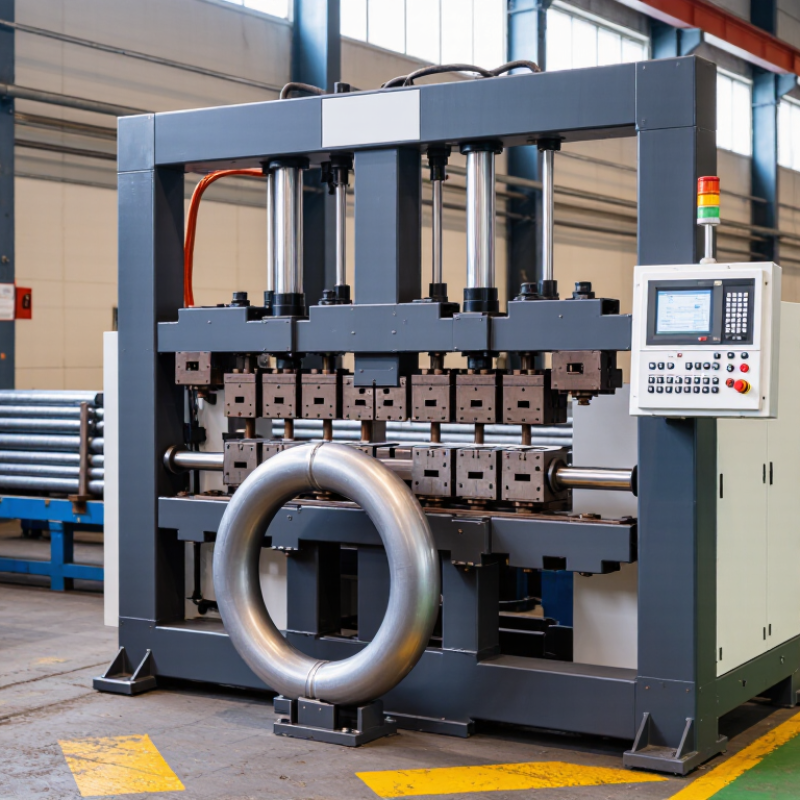
| Basic forming principle | A die supports the pipe while a pressure die, clamp, or forming roller applies force to create a controlled bend around a specified centerline radius. | Common processes include rotary draw bending, roll bending, press bending, and mandrel bending. | Produces repeatable curved sections without cutting and welding multiple straight pieces. |
| Pipe material compatibility | The machine applies controlled force suited to the material strength, wall thickness, and diameter of the workpiece. | Suitable configurations can process carbon steel, stainless steel, galvanized steel, aluminum, and selected copper alloys. | One machine platform can support multiple fabrication requirements when the correct tooling is installed. |
| Typical outside diameter capacity | The pipe is positioned between tooling components sized for its outside diameter and wall thickness. | Compact machines may handle approximately 6–50 mm; medium-duty models commonly cover about 20–100 mm; heavy-duty equipment can exceed 150 mm. | Capacity can be matched to furniture tubing, structural pipe, vehicle components, and industrial assemblies. |
| Minimum bend radius | The die rotates or presses the pipe around a fixed radius while the tooling controls deformation. | Rotary draw bending can commonly achieve approximately 1.5D to 3D centerline radii, where D is the pipe outside diameter; the exact value depends on material and tooling. | Tight bends can reduce assembly size and improve the appearance of frames and tubing systems. |
| Bending angle | The control system stops the die or forming rollers at a programmed position to define the bend angle. | Typical production cycles support bends from a few degrees up to approximately 180°, depending on machine design and tooling clearance. | Accurate angle control helps parts fit consistently during welding and final assembly. |
| Cross-section control | A mandrel, wiper die, pressure die, or correctly matched groove supports the pipe and limits wrinkling, flattening, and wall thinning. | Mandrel bending is generally preferred for tight-radius bends or thin-wall tubing where shape retention is critical. | Maintains internal flow area and improves dimensional consistency. |
| Machine drive system | Hydraulic cylinders, electric servo motors, or a combination of both generate and regulate forming motion. | Hydraulic systems provide high force; electric servo systems provide precise programmable motion and may reduce idle energy use. | The drive type can be selected according to production volume, precision requirements, and pipe size. |
| Control and repeatability | A programmable controller stores bend angles, feed lengths, rotation positions, and multi-step sequences. | Modern CNC tube benders can coordinate several axes; achievable accuracy depends on machine configuration, material springback, and calibration. | Reduces manual measurement and supports consistent batch production. |
| Springback compensation | The machine slightly overbends the pipe or adjusts the programmed position to compensate for elastic recovery after forming. | Springback varies with material grade, yield strength, wall thickness, bend radius, and bending angle. | Improves final angle accuracy and reduces trial-and-error adjustments. |
| Production efficiency | Once tooling and programs are set, the machine repeats feeding, clamping, bending, and unloading steps with limited manual intervention. | Cycle time depends on pipe length, number of bends, bend angle, machine axes, and loading method; automated cells can integrate cutting and end forming. | Usually lowers labor per part and increases output compared with manual heating or multi-piece fabrication. |
| Material utilization | The pipe remains a continuous piece through the bend, avoiding separate elbows and many welded joints. | Waste is mainly associated with end allowances, setup pieces, rejected parts, and cut-length optimization. | Can reduce welding consumables, joint preparation, and scrap in suitable applications. |
| Common applications | The machine forms pipes and tubes into specified geometries for structural, fluid-handling, and equipment assemblies. | Typical uses include handrails, frames, exhaust systems, heat-exchanger tubing, hydraulic lines, roll cages, and furniture components. | Supports both functional flow paths and visually continuous structural designs. |
| Main selection considerations | Machine size and tooling are selected according to pipe diameter, wall thickness, material, bend radius, angle sequence, production volume, and required tolerances. | Verify maximum outside diameter, wall-thickness range, centerline radius, number of controlled axes, motor or hydraulic capacity, tooling availability, and safety features. | Proper matching helps prevent excessive flattening, wrinkling, cracking, springback, and unnecessary equipment cost. |